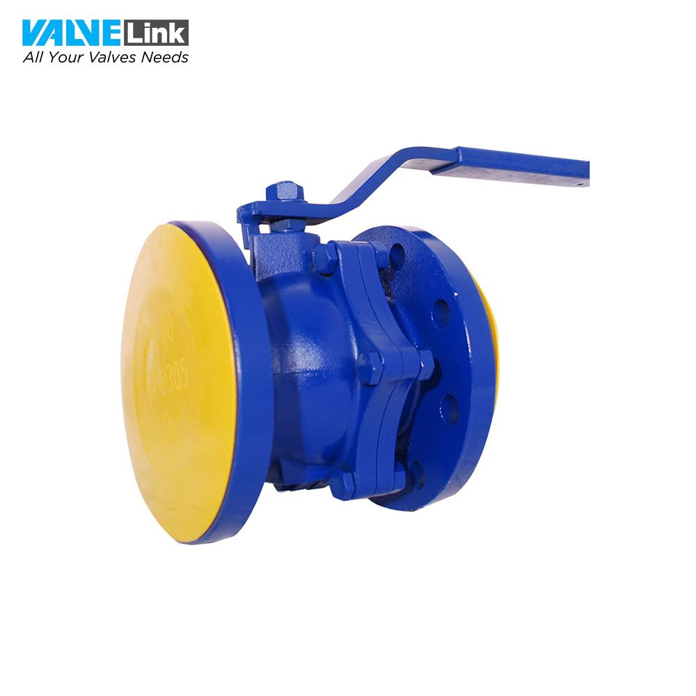
Van bi tay gạt Nordsteam model NST-3PK
Liên hệ báo giá
- Model: NST-3PK
- Xuất xứ: Thổ Nhĩ Kỳ
[TABS_R id=12416]
Mô tả cấu tạo van bi tay gạt model NST-3PK
To have clean fluid like all other valves is also vitally important for ball valves. Therefore, filter should be certainly put before the valve, otherwise, filthy fluid will cause deformation on the surfaces of ball and gasket in a short time. In order to have a long life-cycle for these valves, valves should be turned on and turned off at least once in fifteen days. By taking their structures into consideration, they should be used just for the positions of fully turn-on and turn-off, not for decreasing or increasing. Sudden turn-on and turn-off should be avoided to eliminate the risk of water-hammer. As they consist of three parts, they have advantage of assembling and disassembling easily. They are suitable to use in the media of low pressure steam and gas, in the cold/hot/superheated water installations, the fluids that have no properties of acid and alkalli.
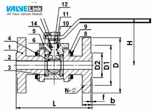
[TABS_R id=12416]Cấu tạo van bi NST-3PK
Thông số kỹ thuật
1-Design and manufacture:DIN EN 13789:2002
2-Face to face dimension:DIN EN 558-1:1995
3-End flange dimension:DIN EN 1092-1:2002
4-Inspection and test:DIN EN 12266:2003
| SPARE PARTS | ||
| No | Description | Material |
| 1 | BONNET | GG25 |
| 2 | SEAT | PTFE |
| 3 | GASKET | PTFE |
| 4 | BALL | STAINLESS STEEL / 304 & 316 |
| 5 | BODY | GGG 40.3 |
| 6 | PACKING | PTFE |
| 7 | SHAFT | STAINLESS STEEL / 2Cr13 |
| 8 | BOLT | 35 |
| 9 | NUT | 45 |
| 10 | VERGE RING | 20 |
| 11 | LOCATED BLOCK | A3 |
| 12 | WASHER | A3 |
| 13 | NUT | 45 |
| 14 | HANDLE | A3 |
| DIMENSIONS | |||||||||
| SIZE | PN 16 | ||||||||
| L | D | D1 | D2 | b | H | N-Ø | f | ||
| DN15 | 130 | 95 | 65 | 45 | 14 | 105 | 4*14 | 2 | |
| DN20 | 150 | 105 | 75 | 58 | 16 | 108 | 4*14 | 2 | |
| DN25 | 160 | 115 | 85 | 68 | 16 | 112 | 4*14 | 2 | |
| DN32 | 180 | 140 | 100 | 78 | 18 | 118 | 4*18 | 2 | |
| DN40 | 200 | 150 | 110 | 88 | 18 | 125 | 4*18 | 3 | |
| DN50 | 230 | 165 | 125 | 102 | 20 | 137 | 4*18 | 3 | |
| DN65 | 290 | 185 | 145 | 122 | 20 | 160 | 4*18 | 3 | |
| DN80 | 310 | 200 | 160 | 138 | 22 | 180 | 8*18 | 3 | |
| DN100 | 350 | 220 | 180 | 158 | 24 | 205 | 8*18 | 3 | |
| CONNECTION | FLANGED | |||||||||||
| SIZES | DN15 | DN20 | DN25 | DN32 | DN40 | DN50 | DN65 | DN80 | DN100 | DN125 | DN150 | DN200 |
| WEIGHTS (KGS) | 2 | 3 | 4,3 | 7,5 | 9 | 13,3 | 19,5 | 28 | 40 | |||
| OPERATING CONDITIONS | |
| MAX. ALLOWABLE PRESSURE PMA (BAR) | 24 |
| MAX. ALLOWABLE TEMPERATURE TMA (ºC) | -15 ~ 200 ℃ |
| MAX. OPERATING PRESSURE PMO (BAR) | 16 |


